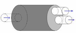
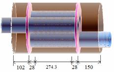
Dual tailpipe muffler (Figure 1a)
The single inlet pipe and the two tailpipes are of 50 mm diameter; the chamber is of 150 mm diameter and 225 mm length. The center of the inlet pipe is on the chamber axis, the centers of the two tailpipes are at 12.5 mm radius from the chamber axis and at polar angles of 90o and 330o. Wu et al (Applied Acoustics 69(2008) 173-178) computed the transmission loss TL) of this muffler by ANSYS, employing 3005 linear elements and 14675 nodes. Denia and Selamet (Applied Acoustics 69 (2008) 280-281) also computed the TL of the same muffler by SYSNOISE, using 5389 quadratic finite elements and 8526 nodes.

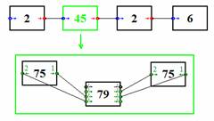
A block diagram model of this muffler is shown in Figure 1b. Elements 2 and 70 model the pipes and the element 45 models the chamber. Element 75 can model any prismatic 3-D cavity with any number lateral or axial pipe connections with given azimuth and elevation orientation. Sections can be of any shape, although in the example considered they are all circular.
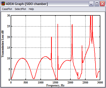
The TL of the muffler computed by using 6 modes and assuming a speed of sound of 343.7 m/s is shown in Figure 1c. This is very close to the TL spectrum computed in the above mentioned SYSNOISE solution.
Through-flow chamber (Figure 2a)
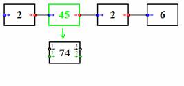
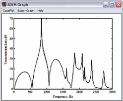
This muffler is taken from Kirby (Journal of the Acoustical Society of America 114 (2003) 200-209). The chamber is elliptical having major and minor axes of 2a=220 mm and 2b=120 mm, respectively. The chamber length is L=350 mm. The internal diameter of the perforated pipe is D=74 mm, the side-branch extensions are negligible (L1=L2=0) and the eccentricity is zero, that is, e=0. The perforations are of 3.5 mm diameter and 1 mm thickness, the open area porosity of the perforated length, L, being 26.3%. The annulus is packed with basalt and the perforated pipe carries a mean flow of Mach number 0.15. In the block diagram model (Figure 2b), blocks 2 model the solid pipe sections. Element 74 can model sound transmission in 3-D in any number of perforated pipes arranged in singly or doubly communicating arrangements in a solid casing. The TL of this muffler computed by ADEM by using six modes is shown in Figure 2c. This is in close agreement with the theoretical and experimental results of Kirby.


A through-flow chamber is also used frequently with an empty annulus. In a case published by Albeda, Denia, Torres and Fuenmayor (Journal of Sound and Vibration 303 (2007) 614-631), the elliptical major and minor axes are 2a=230 mm and 2b=130 mm and the perforated pipe carries no mean flow. The perforate length is L=200 mm, the internal diameter of the perforated pipe is D=50 mm, the side-branch lengths are L1=80 mm, L2=40 mm and e=0.
The apertures are circular of 3 mm diameter and 1 mm thickness and have an open area porosity of 5% over L. The block diagram model in Figure 2b still applies for this muffler, but with the packing data turned off in the datasheet of element 74. TL spectrum of the muffler as computed by using this model using four modes is shown in Figure 2d. This is in close agreement with the results of Denia, et al.
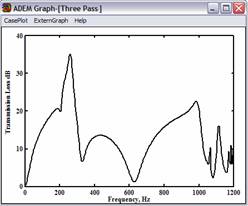
Three-pass muffler (Figure 3a)
This muffler consists of three perforated pipes mounted on two 12.7 mm thick solid baffle plates in a solid circular casing. The perforated pipes are all 0.8 mm thick and have an internal diameter of 48.9 mm. The casing diameter is 165.1 mm, and the pipes are arranged at an angular pitch of 120o, around a center circle of radius of 39.69 mm. The perforate segments in the center chamber contain 448 circular holes of 2.47 mm diameter, giving an open area porosity of 4.5%. Experimentally and theoretically determined TL spectrum of this muffler has been presented by Selamet, Easwaran and Falkowski (Journal of the Acoustical Society of America 105 (1999) 1548-1562). Block diagram model of this muffler is shown in Figure 3b and the TL spectrum computed by using three modes in Figure 3c. The latter is in good agreement with the experimental results presented in the above mentioned article.
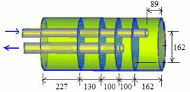
A flow-reversing muffler (Figure 4a)
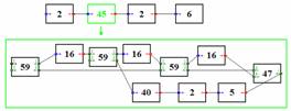
This example is from Elnady, Abom and Allam (Journal of Vibration and Acoustics ASME 192 (2010)). The casing is elliptical with minor and major axes of 100 mm and 290 mm. The inlet pipe diameter is 45 mm and contains a perforated segment of length 90 mm having 154 apertures in the second chamber from left. The outlet pipe is of diameter 57 mm and contains perforated segments of 144 mm with 288 apertures in the first chamber from left and another segment of 72 mm with 144 apertures in the third chamber from left. From left to right, the baffles contain 50, 72, 72 and 42 apertures. All apertures on the pipes and baffles are circular of 5 mm diameter and 1.5 mm thickness. In the block diagram model (Figure 4b), element 59 models the perforated pipe segments, element 16 models the baffles and element 40 models the flow reversing chamber. The TL spectrum computed by using the dimensions specified for the case of no mean flow is shown in Figure 4c. It is in good agreement with the results presented in the quoted source article.

Chamber with side-inlet and side-outlet (Figure 5a)
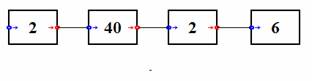
Figure 5a shows a so-called side-inlet side-outlet expansion chamber. A block diagram model of this chamber is shown in Figure 5b. Element 40 is hybrid element which implements element 75 when invoked in the 3-D mode (see Figure 1).

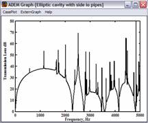
A circular version of this side-inlet side-outlet chamber is studied analytically by Yi and Lee (Journal of the Acoustical Society of America 79 (1986) 1299-1306). The dimensions of the muffler are: 2a=2b=122 mm, L=300 mm, d1=d2=20.66 mm, L1=150 mm, L2=225 mm. The inlet and outlet pipes are radial, the angle between their axis being 90o. The TL spectrum shown in Figure 5c is computed by using the first 20 transverse chamber modes. It is in exact agreement with the corresponding results presented in the above quoted article.
The TL spectra shown in Figure 5d show the effect of changing the geometry of the chamber section, the diameter and orientations of the inlet and outlet pipes and their relative positions remaining the same. The blue and red curves correspond, respectively, to an elliptic and oval chamber with 2a=157.5 mm and 2b=94.5 mm. The oval section has an ovality ratio of is 8.5.

