Block diagram models of duct systems, mufflers, silencers, and resonators are constructed on the System Model Interface (SMI) by simple mouse actions. SMI has several layers. The block diagram of the complete system is drawn in layer 1 as a cascade, or a tree network of two-port blocks, which may themselves be any network of two-port and multi-port blocks in 1-D or 3-D. The process of generating mathematical models from block diagrams is carried out by the computer. This involves complex mathematical operations, which are often published as research articles in scientific journals.

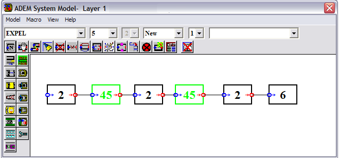
For example, consider the cold end of the exhaust line of a passenger car consisting of front (circular) and rear (oval) mufflers, as shown in Figure 1. Figure 2 is a block diagram of this duct system as drawn in layer 1 of SMI. Blocks are created, deleted, joined, moved, resized, rotated, etc., by clicking on toolbar buttons or drop-down list items. Ports of the blocks, the small circles on sides of blocks, can be connected by dragging the mouse from one port to the other. Little arrows besides the blocks indicate the default positive acoustic flow direction. These directions can be changed by the user by clicking on the ports so that the continuity of flow is maintained.
Blocks have names as well as numbers. For example, the block numbered 2 [PIPEL] models a uniform duct. The block numbered 45 [UserMacro] is a two-port that may be any subsystem consisting of two-ports and/or multi-ports in 1-D or 3-D. In Figure 2, the UserMacros [45] represent, left to right, the circular and oval mufflers. A UserMacro may be saved with a name so that it can be used later as an acoustic element. The UserMacro concept, apart from simplifying the block diagram in layer 1, provide a component-based modeling capability, which is a convenient tool for teamwork in specific projects and for customization.
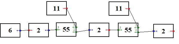
Block diagrams of UserMacros (1-D or 3-D) are constructed in sublayers of SMI. For example, Figure 3 shows a block diagram of the UserMacro which models the rear muffler in Figure 1. A UserMacro becomes active when it is linked to its sublayer. Then the color of its sides turns bright green. A UserMacro [45] does not require any data input. UserMacroX [35] is the same as UserMacro [45] except that it has its layer number as input parameter. This enables running of different subsystem prototypes in batch.

Sound source
The acoustic source driving a duct system can be defined in ADEM explicitly or implicitly.
The explicit method
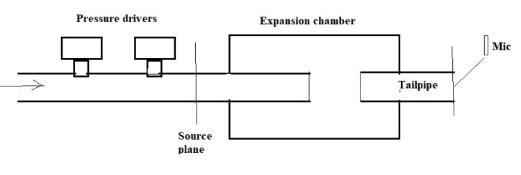
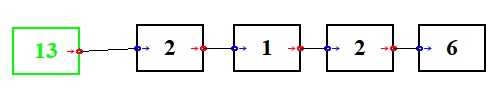
Any multiple-input-single-output duct system with spectral sources (defined subsequently) is represented by the generic one-port element called SourceMacro [13]. This is connected as the terminal element on the source side of the block diagram in layer 1. For example, Figure 4a is a schematic of a laboratory setup, where the acoustic field in a duct system is generated by two pressure drivers in tandem, for the measurement of some acoustic parameters of the system. The SourceMacro [13] is used to model the upstream side of the (equivalent) source plane as shown in Figure 4b. A SourceMacro [13] is similar to a UserMacro [45] in that, it must be linked to a sub-layer of SMI, where its block diagram model is drawn. Figure 4c is a block diagram of the SourceMacro [13] in Figure 4b.
Two-port acoustic sources are applied by using the element SOURCEL [26], the characteristics of which may be based on actuator-disk models or measurements. This may co-exist with a SourceMacro [13] or an implicitly defined one-port source or may be the primary source.
The implicit method
If a duct system is driven by a one-port source, the program assumes that it is applied at the inlet node of the system, which is defined as the unconnected inlet node on the source side of the block diagram in layer 1. For example, in Figure 2 the source is applied by the implicit method at the inlet node of element 2, which corresponds to the inlet of the circular muffler in Figure 2.
The type of an implicit source is selected from the main menu and the source data are input in respective datasheets (see Video 1). The following source types can be applied implicitly:
Piston
Rigid piston driven by arbitrary velocity or displacement signal.
Spectral
One-port source with frequency dependent impedance and pressure strength. Simple tools are provided for calculating crisp spectral source characteristics of loudspeakers and the crisp or fuzzy equivalent source characteristics of engine exhausts and intakes. There is also a tool for moving multiple crisp spectral sources to an equivalent source plane. Steady and non-steady spectral one-port sources, the characteristics of which are determined from the microphone signals in source measurements can be applied implicitly and Campbell diagrams can be produced in case of non-steady sources.
Orders
This is a non-steady one-port spectral source. Its datasheet allows input of the equivalent source characteristics corresponding to the selected orders of fluid machinery rotational speeds. Typical applications include prediction of the intake and exhaust noise of automobiles as function of the engine speed.
Power
Applies a given acoustic power spectrum at the source plane, irrespectively of the load.
Undefined
This option is chosen when calculating an acoustic parameter that do not depend on the source characteristics (e.g., transmission loss of a 1-D system).
Acoustic element database
The following table summarizes the categories of the over 60 acoustic elements contained in the database of the software. Each category includes one-dimensional and three-dimensional elements with mean flow. Using this database, users can create an infinity of new elements.
| Category | Some features |
| Perforated pipe packs | Any number of perforated pipes enclosed in hard- or soft-walled casing in singly- or doubly-coupled, or arbitrary communication topology; mean cross-flow or grazing flow configuration; sound absorbent material application for dissipative units; discrete or continuous perforate models. |
| Area changes | Open or closed; through flow or flow reversing; multiple inlets or outlets; side-inlet or side-outlet |
| Junctions | With any number of connecting ducts including branch and splitter configurations |
| Pipes and ducts | Uniform or non-uniform; mean temperature and pressure gradients; narrow viscothermal; lined; open or porous walls; distensible walls. |
| Macros (user formulated) | Generic passive two port (based on ADEM database): generic passive two-port (measured or FEM or BEM based); generic active one-port (equivalent of arbitrary miso system) |
| Sources | 1-port: 2-port |
| Boundary | Open (flanged or unflanged, intake or exhaust with mean flow); closed; pressure-release, anechoic; measured; multi-mode cut-on |
| Open end radiation | Free-field; fractional free-field; diffuse field. |
| Compounds | Several common mufflers, chambers and resonators |
| Baffles | Perforated uniformly or over regions |
| After treatment | Catalytic converter; Diesel particulate filter |
Input datasheets
Element data are entered in element datasheets, which open when you click within the area of a block. Element datasheets have formula input capability and error filters for number input format. A typical input datasheet is shown in Figure 5. Detailed definitions of the input parameters on each datasheet are accessed on-line by clicking on the Help button. The input fields accept algebraic formulas in APL language and are checked for syntax. The mean temperature and the mean pressure in elements are input only for a reference operational point and no input is required for the mean flow velocity.

