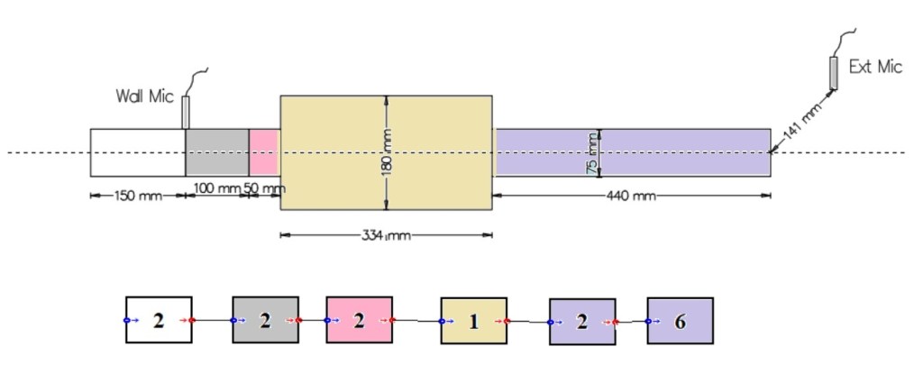
Expansion chamber excited by a runup signal
The inlet duct of the expansion chamber shown in Figure 1 is connected to an engine intake. The engine is runup through a speed range in 30 seconds. The mean flow varies with the engine speed.
An acoustic block diagram model of the expansion chamber is also shown in Figure 1. The sound pressure radiated from the tailpipe is calculated by ADEM at the external microphone position, when the acoustic pressure at the wall mounted microphone position is as Signal 1.
Play Signal 1 to hear the sound created in the inlet duct at the section of the wall mounted microphone.
Play Signal 2 to hear the sound computed by ADEM at the external microphone position in an anechoic chamber.
Play Signal 3 to hear the sound measured by the external microphone.
A production air duct excited by a runup signal
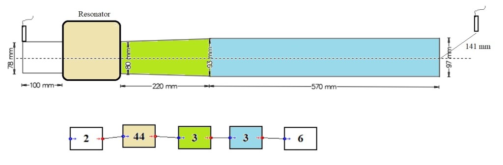
Figure 2 shows a schematic of the intake system duct of a passenger car. The resonator has an irregular geometry and its wave transfer matrix is measured by using the four microphone method and the microphone signals are processed in the measurement module of ADEM. The elements of the measured wave transfer matrix are shown in Figure 3.
Play Signal 1 above to hear the sound at the wall mounted microphone.
Play Signal 4 to hear the sound computed by ADEM at the external microphone position in an anechoic chamber.

Aftermarket tripass exhaust mufflers
Several tripass after market exhaust mufflers are mounted on a car with a 4 cylinder 85 kW gasoline engine at the same position on the exhaust line and the sound radiated from the exhaust tailpipe is measured, at 500mm and 45 degrees from the tailpipe outlet center, as throttle opened momentarily to 4000 rpm (Source: AutoSpeed).
Measured unmuffled sound
Measured with Muffler 1 ![]() mounted
mounted
Measured with Muffler 2 ![]() mounted
mounted
Measured with Muffler 3 ![]() mounted
mounted
